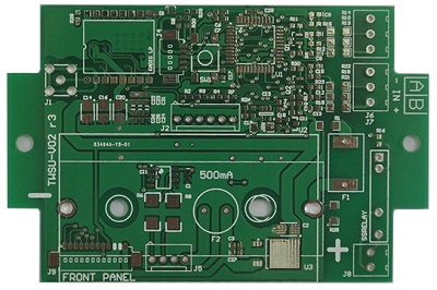
 PCB
PCB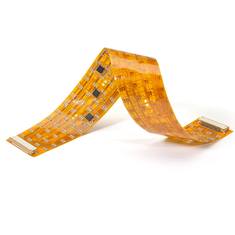 FPC
FPC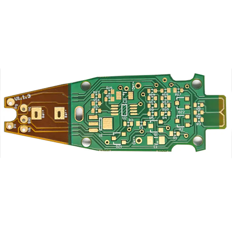 Rigid-Flex
 FR-4
FR-4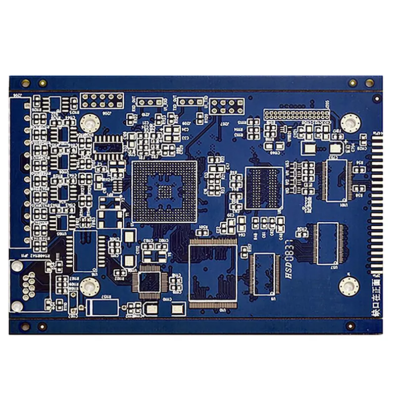 HDI PCB
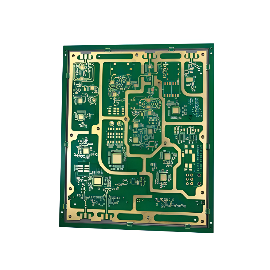 Rogers High-Frequency Board
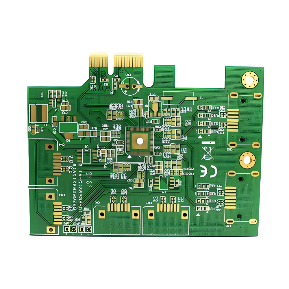 PTFE Teflon High-Frequency Board
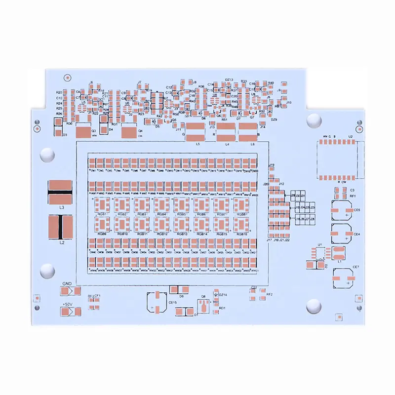 Aluminum
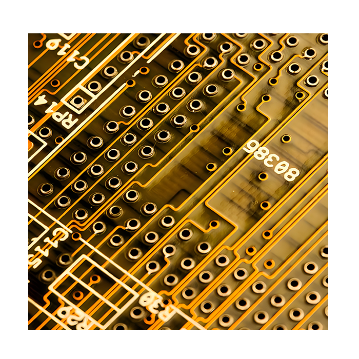 Copper Core
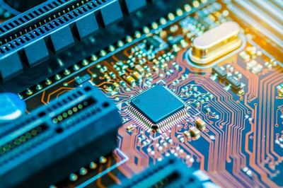 PCB Assembly
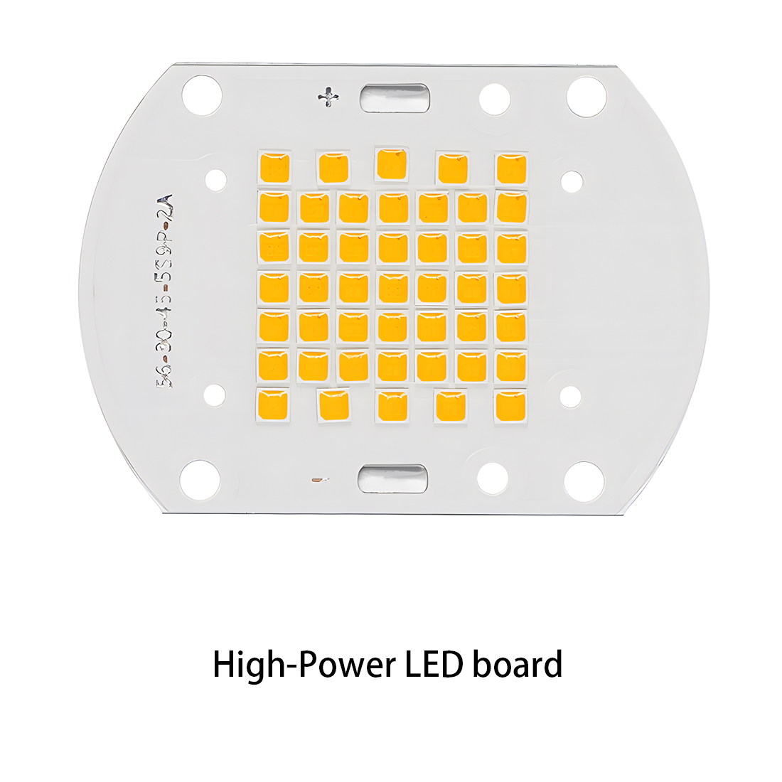 LED light PCBA
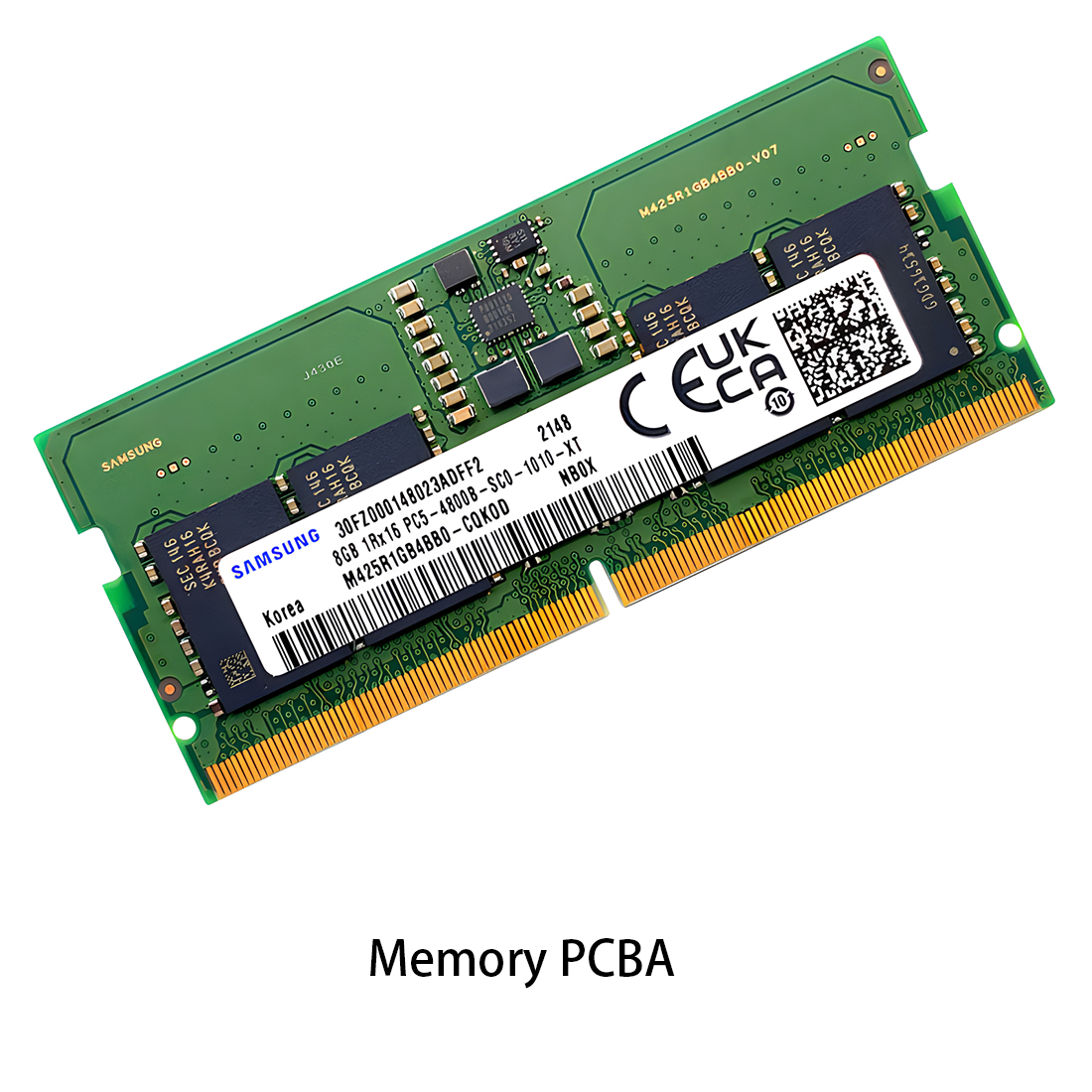 Memory PCBA
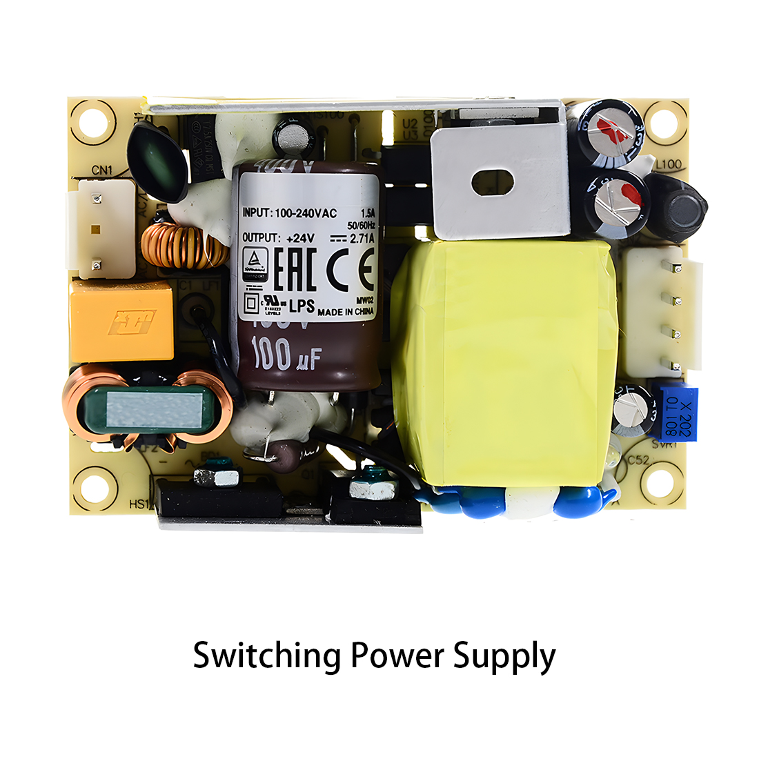 Power Supply PCBA
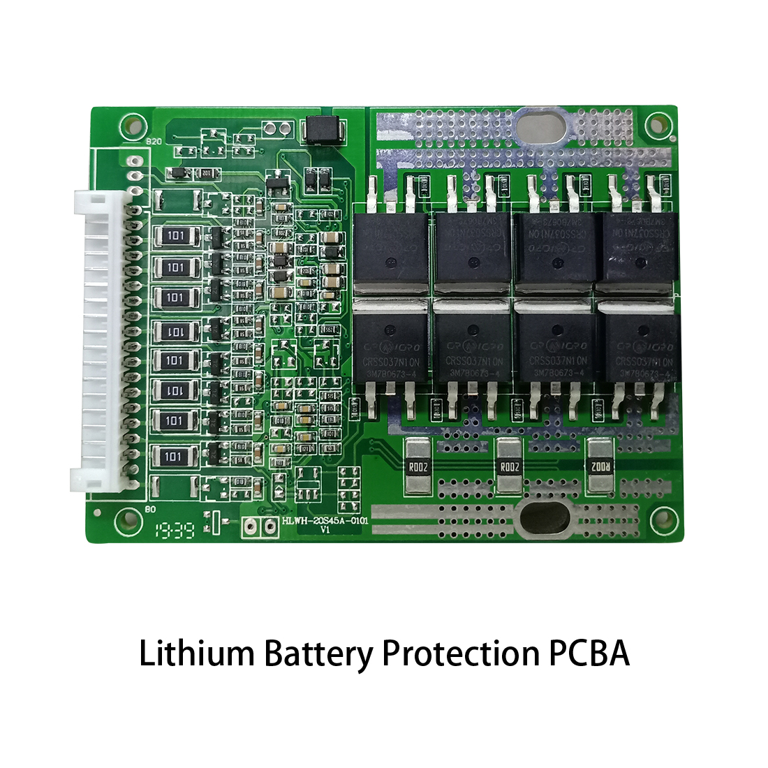 New Energey PCBA
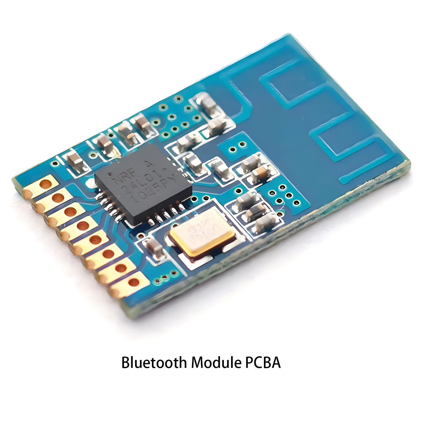 Communication PCBA
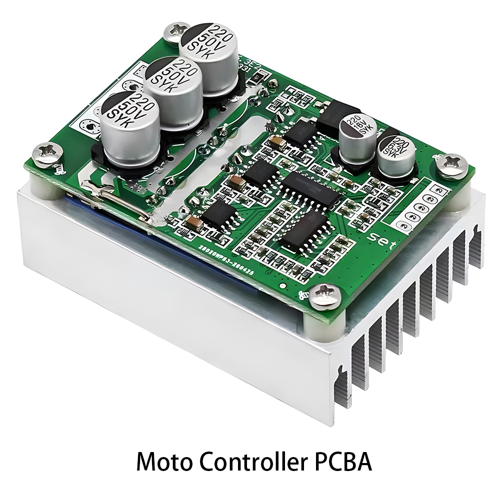 Industrial Control PCBA
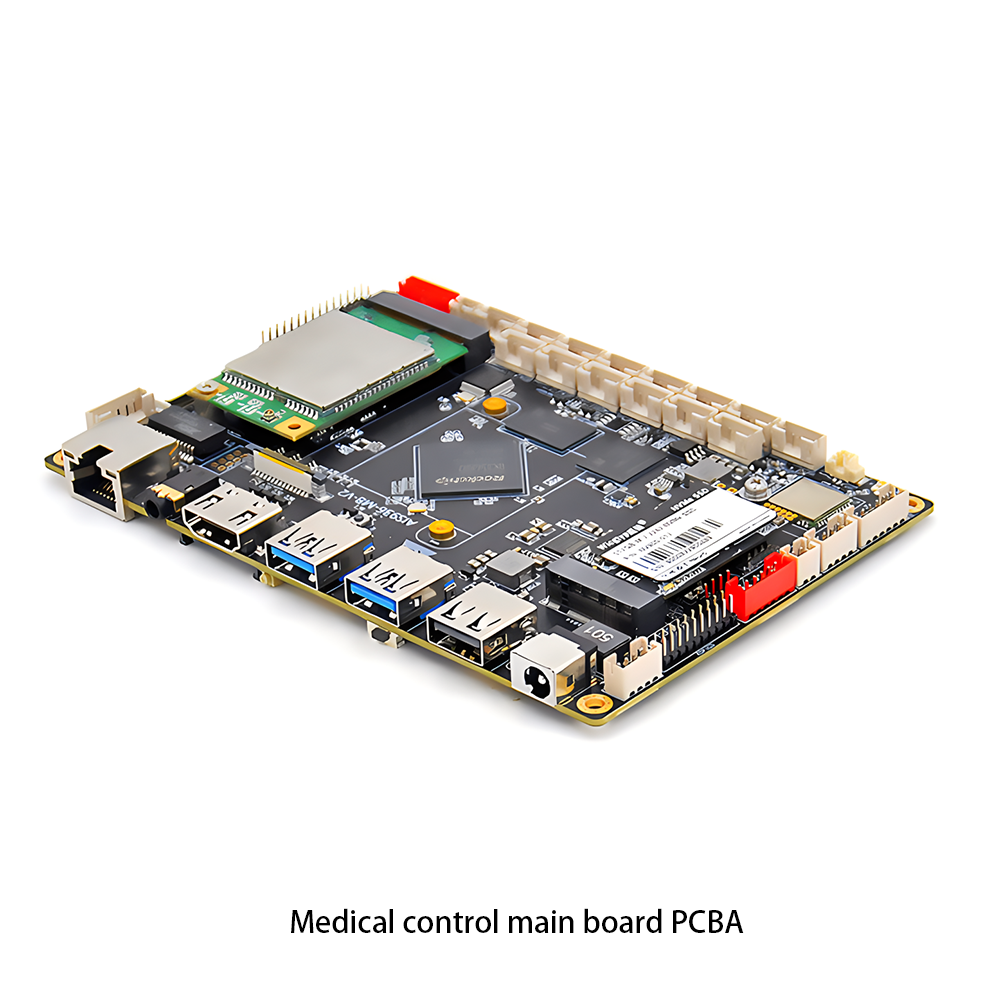 Medical Equipment PCBA
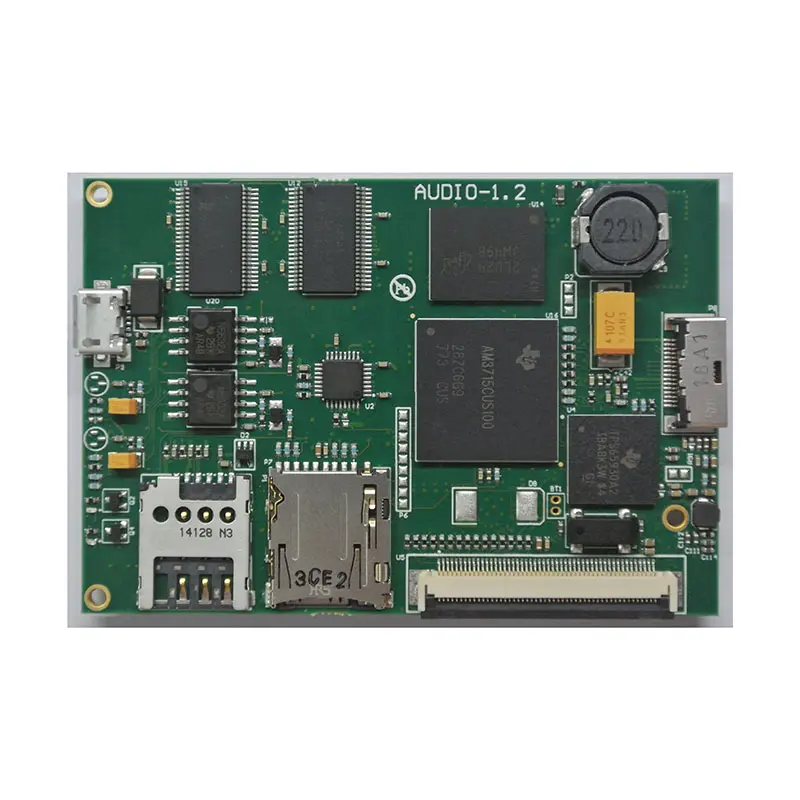 Testing Service
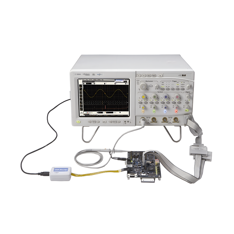 PCBA Testing Service
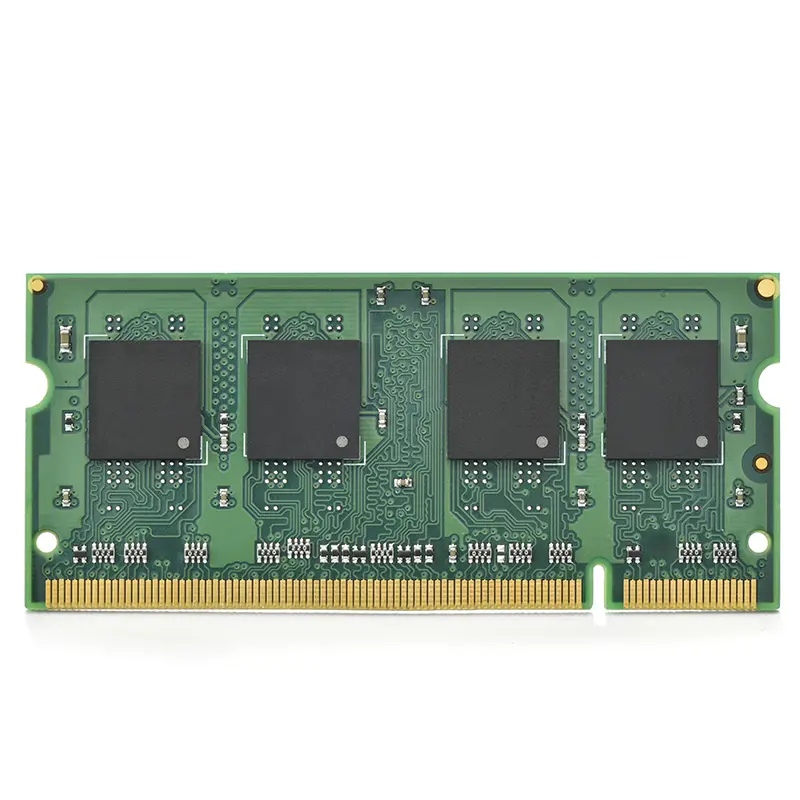 Certification Application
 RoHS Certification Application
 REACH Certification Application
 CE Certification Application
 FCC Certification Application
 CQC Certification Application
 UL Certification Application
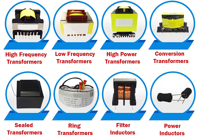 Transformers
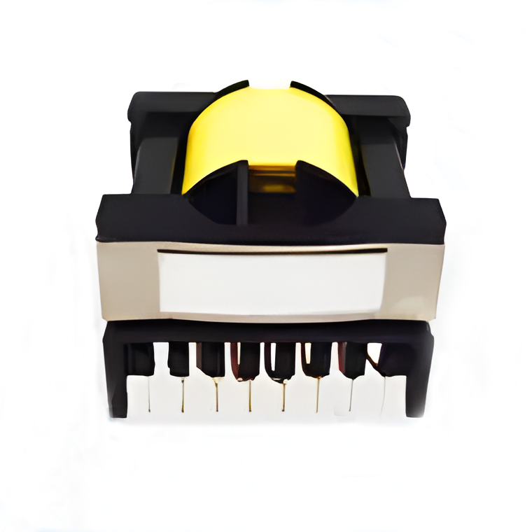 High Frequency Transformers
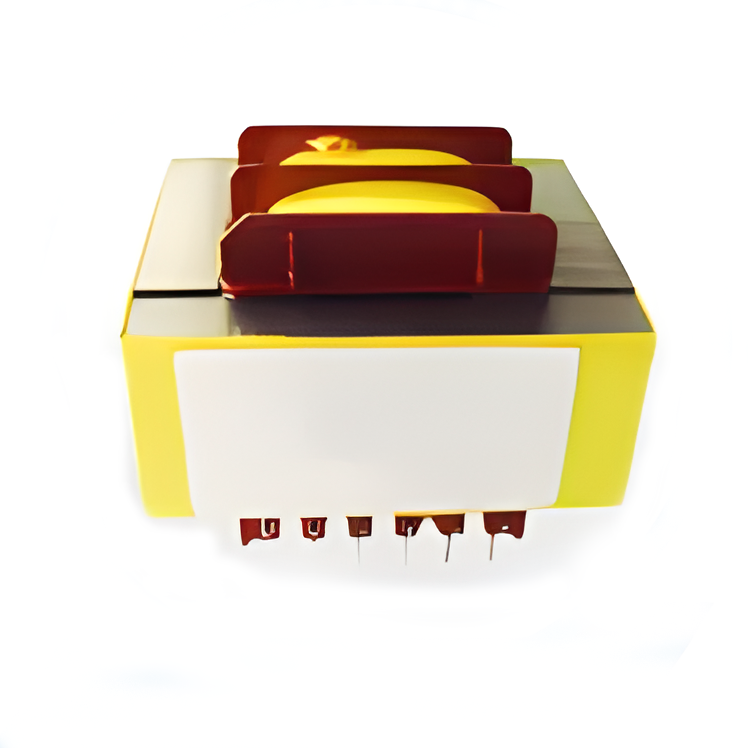 Low Frequency Transformers
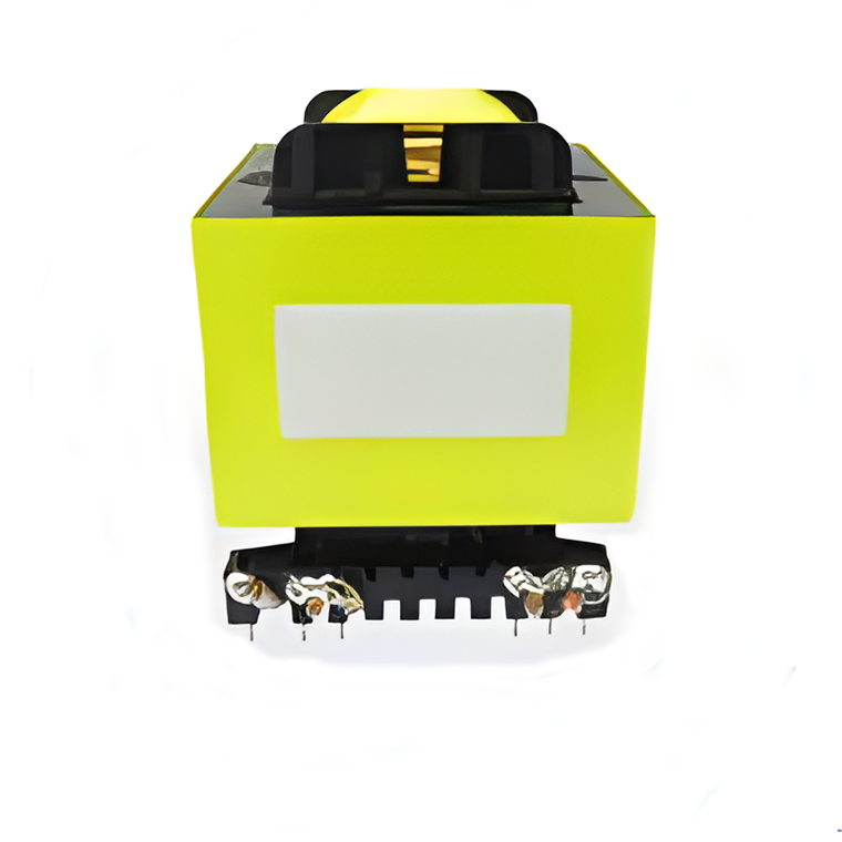 High Power Transformers
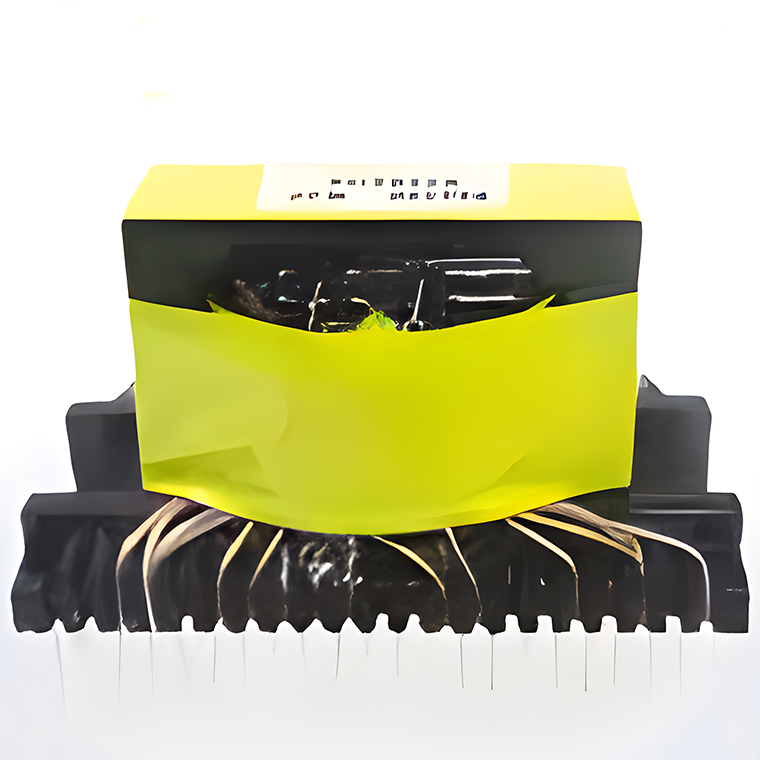 Conversion Transformers
 Sealed Transformers
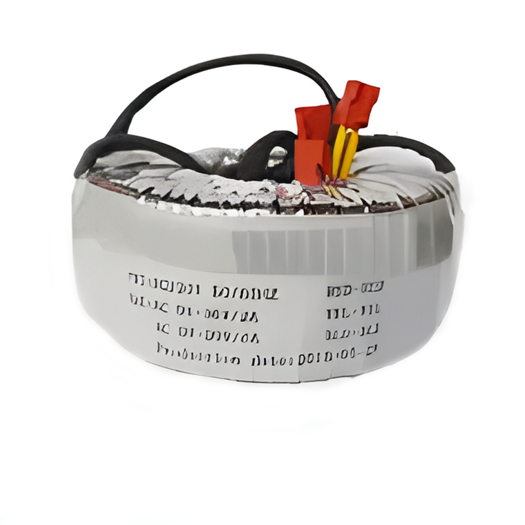 Ring Transformers
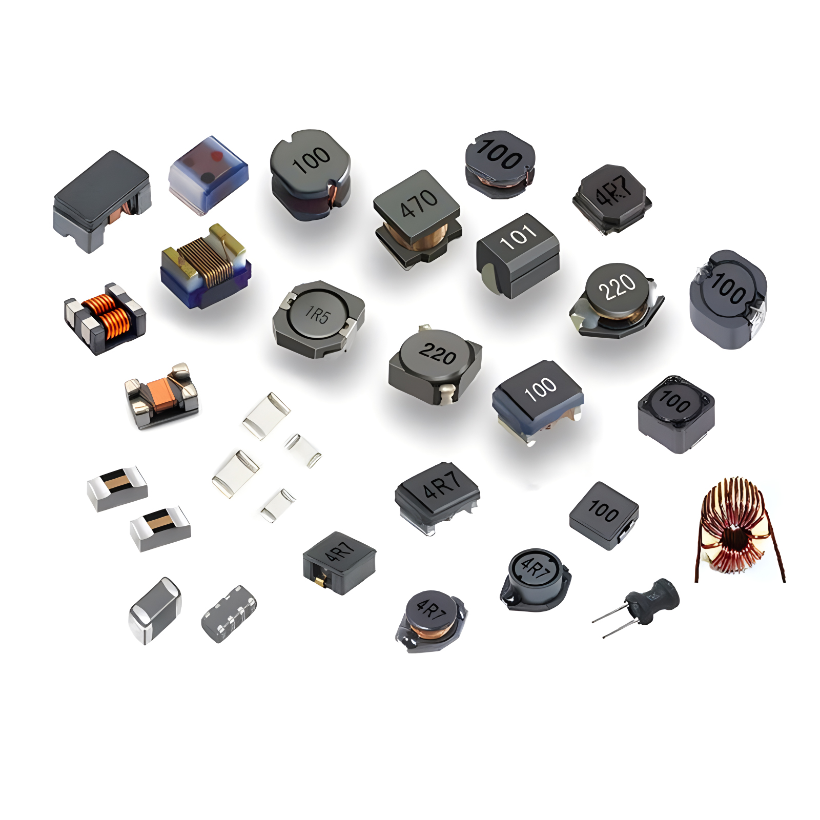 Inductors
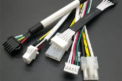 Wires,Cables Customized
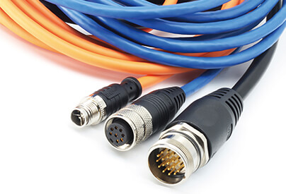 wires-cables
PCBA Electrical Test, or the electrical testing of Printed Circuit Board Assemblies, refers to a series of tests conducted after the assembly of a printed circuit board. These tests aim to ensure that the PCBA meets design requirements in terms of electrical connectivity, functional integrity, and overall performance. Below are the primary functions of PCBA electrical testing:
Continuity Testing: Ensures the connectivity of all circuit paths, checking for open or short circuits.
Component Function Testing: Validates that all electronic components operate as intended according to the design specifications, such as resistance values, capacitance values, forward voltage drops of diodes, etc.
Circuit Function Testing: Confirms the normal functioning of the circuit board through input signals and observing output responses, such as truth tables for logic gates, gain of amplifiers, cutoff frequencies of filters, etc.
Signal Integrity Testing: Checks whether signal transmission paths meet design requirements, including rise times, fall times, delay times, reflections, crosstalk, etc.
Power and Load Testing: Tests the stability and load capacity of power circuits, ensuring that power supplies function properly under various load conditions.
Withstand Voltage Testing: Verifies the insulation performance of the circuit board under high voltage conditions, ensuring it can withstand voltages within the design specifications.
Thermal Performance Testing: Monitors temperature distribution across the circuit board while operational, ensuring there is no risk of overheating.
Safety and Compliance Testing: Ensures that the circuit board adheres to relevant safety standards and regulatory requirements.
Key Equipment
The main equipment involved in conducting PCBA electrical tests includes:
In-Circuit Test (ICT) Equipment: ICT testers use bed-of-nails fixtures to directly contact test points on the circuit board, testing parameters of resistors, capacitors, diodes, transistors, and detecting circuit continuity.
Function Test (FCT) Equipment: FCT stations often include customized fixtures and test programs to verify circuit board functionality, such as processor operation, response of input/output interfaces, etc.
Boundary Scan Testing: Utilizes JTAG (Joint Test Action Group) technology for diagnosing and testing circuit boards, particularly suitable for testing packaged components like BGAs.
Automated Optical Inspection (AOI) and Automated X-ray Inspection (AXI): Primarily focused on physical defects, these indirectly support electrical testing by ensuring proper component installation and solder joint quality, enhancing the accuracy of electrical tests.
Signal Analyzers: Such as oscilloscopes and spectrum analyzers, used for monitoring signal quality and characteristics.
Power Supplies and Load Simulators: Used to test power management and load-bearing capabilities of the circuit board.
Environmental Test Equipment: Like temperature/humidity chambers, used to test circuit board performance under varying environmental conditions.
Flying Probe Test (FPT): Uses mobile probes to test the electrical characteristics of circuit boards, suitable for small batches or prototype circuit boards without requiring dedicated fixtures.
Through these devices, PCBA electrical testing comprehensively evaluates the electrical properties and functions of circuit boards, ensuring their performance and reliability in practical applications.


