 PCB
PCB Rigid-Flex
 HDI PCB
 FR-4
FR-4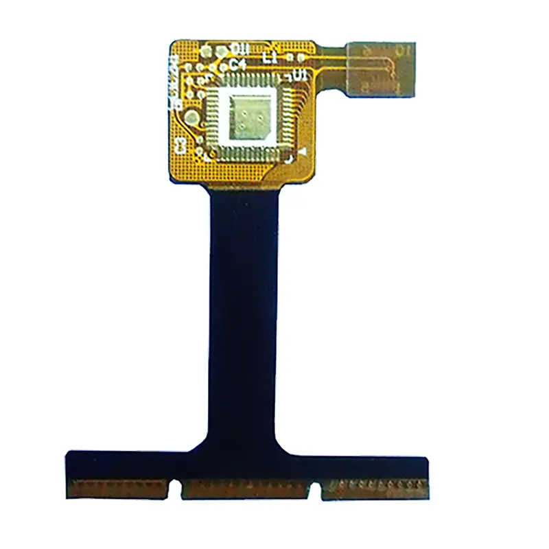 FPC
FPC Aluminum
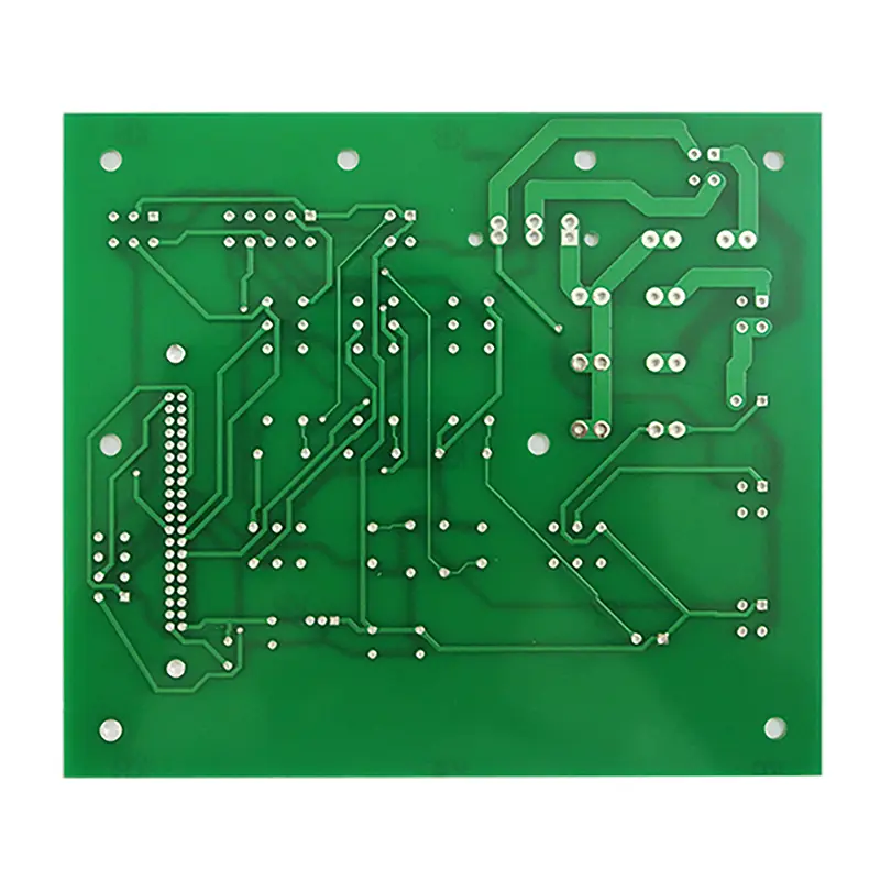 Advanced PCBs
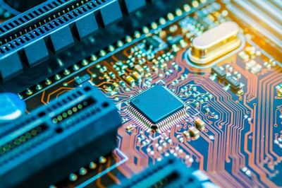 PCB Assembly
 SMT Production
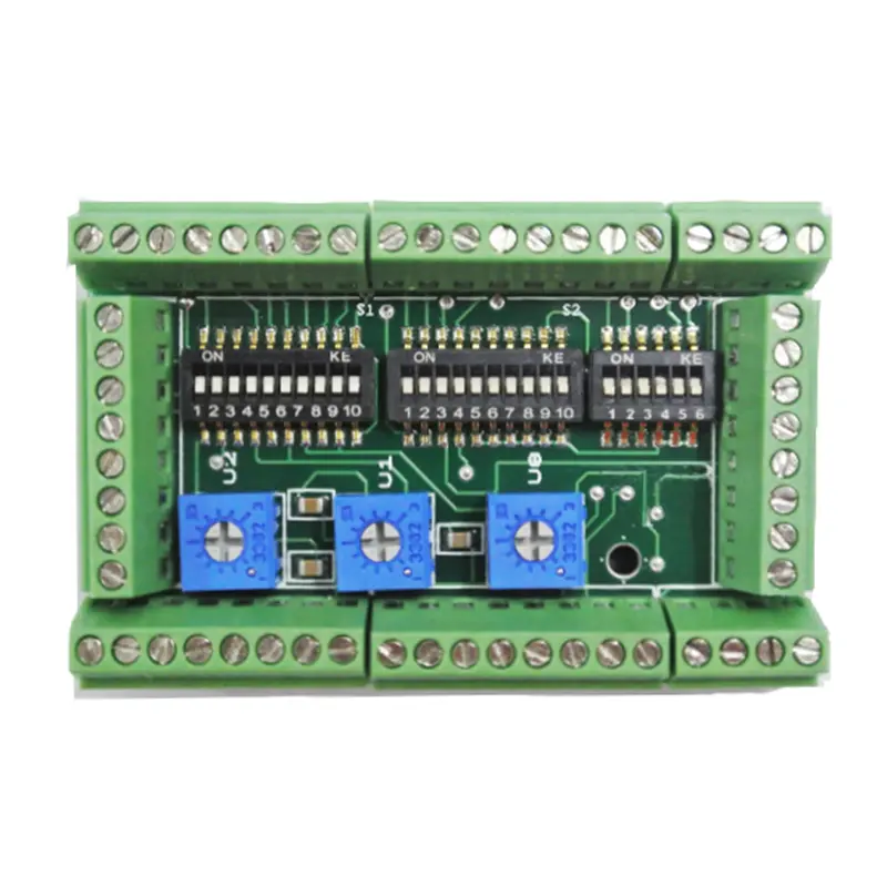 DIP Production
 Testing Service
 PCBA Testing Service
 Certificate Applying
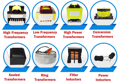 Transformers
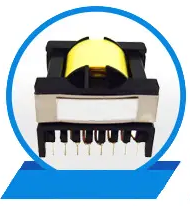 High Frequency Transformers
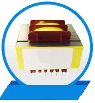 Low Frequency Transformers
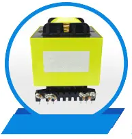 High Power Transformers
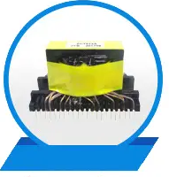 Conversion Transformers
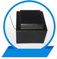 Sealed Transformers
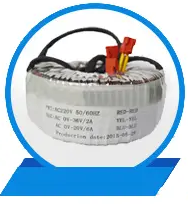 Ring Transformers
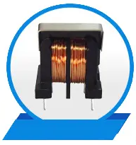 Filter Inductors
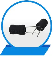 Power Inductors
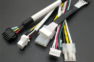 Wires,Cables Customized
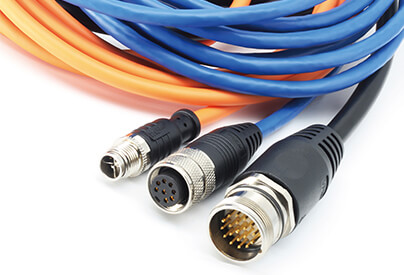 wires-cables
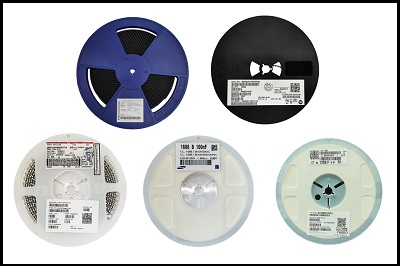 Components sourcing
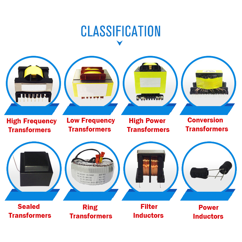


Conversion Transformers
Classifications
PCB conversion transformers can be classified based on various criteria:
By Function: Voltage transformers for stepping up or down voltages, isolation transformers for providing galvanic isolation, and auto transformers that use a single winding for both input and output to save on copper and size.
By Construction: Open-frame, encapsulated, or potted transformers, differing in their protection levels against environmental factors like dust, moisture, and mechanical stress.
By Frequency Range: Low-frequency transformers (50/60Hz) for mains power applications and high-frequency transformers (kHz to MHz) used in switch-mode power supplies (SMPS).
Manufacturing Techniques
The manufacturing process of PCB conversion transformers involves several stages:
Design & Simulation: Using software tools to design the transformer, considering parameters such as voltage, current, frequency, and desired efficiency.
Core Selection: Ferrite or iron powder cores are commonly used, chosen based on the required performance and operating frequency.
Winding: Automated machines wind the wire onto the core according to the designed pattern, ensuring precise control over the number of turns and insulation.
Assembly: Windings are mounted onto the PCB, often using automated pick-and-place machines, followed by soldering.
Testing: Comprehensive testing includes insulation resistance, dielectric strength, and functional tests to ensure compliance with safety standards.
Performance Attributes
Key performance attributes of PCB conversion transformers include:
Efficiency: The ratio of output power to input power, with higher efficiency translating to less energy loss and heat generation.
Voltage Regulation: The ability to maintain a stable output voltage despite changes in load or input voltage.
Insulation Resistance: Ensures safe operation by preventing electrical leakage between windings and to ground.
Frequency Response: Determines the transformer's ability to handle a range of frequencies without significant degradation in performance.
Distinctive Advantages
PCB conversion transformers offer several advantages:
Compactness: Their integration directly onto PCBs significantly reduces the overall size and weight of electronic devices.
Cost-Effectiveness: Mass production techniques and standardized designs lower manufacturing costs.
Ease of Integration: Seamless integration with other PCB components simplifies design and assembly processes.
Flexibility: Customizable to meet specific voltage and power requirements of diverse applications.
Key Application Domains
PCB conversion transformers find extensive use across a myriad of industries and devices:
Consumer Electronics: In smartphones, laptops, TVs, and home appliances for power supply and voltage regulation.
Industrial Automation: For control systems, motor drives, and PLCs, ensuring stable power supply and isolation.
Medical Equipment: Vital in medical devices requiring precise voltage control and electrical isolation for patient safety.
Renewable Energy Systems: Used in solar inverters and wind turbine controllers for efficient power conversion.
Telecommunications: Essential in network equipment, routers, and base stations for power supply and signal transmission.
12